Lines in technical drawings are part of a specialized graphic language that is standardized throughout industry. Correct usage of this alphabet of lines is essential whether you use traditional drafting methods or CAD.
The Language Of Lines Basic Blueprint Reading
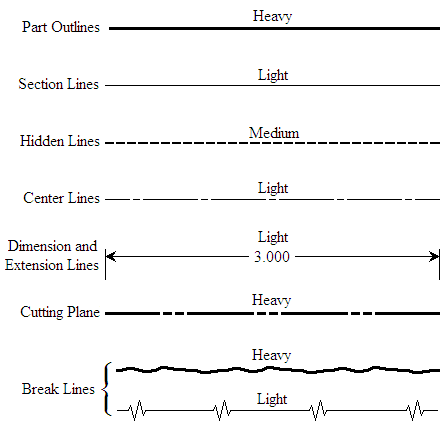
Line weight is the thickness of the line.
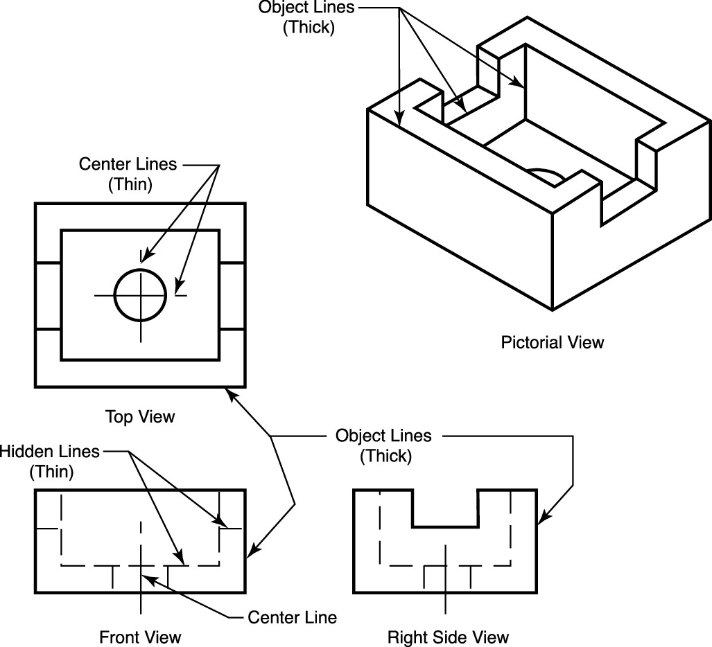
. An engineering drawing is a type of technical drawing that is used to convey information about an object. Phantom long dash two short dashes repeat depict features not part of the design but shown for clarity. Object lines Object lines Figure 3 are the most common lines used in drawings.
Thick and visible line. A hidden line also known as a hidden object line is a medium weight line made of short dashes about 18 long with 116gaps to show edges surfaces and corners which cannot be seen. 1o a visible edge being represented by a full line and an invisible one by a dotted line ie a line made up of short dashes.
The first dimension line should be approximately 12 mm 06 in from the object. Each style can be divided into different types. A line on a drawing always indicates either an intersection of two surfaces as in the projection of a prism or a contour as in the projection of a cylinder fig.
It is assumed that an object is placed in front of a screen and light projected on the object assuming that the rays of light to be parallel to each other and perpendicular to the screen then a true shadow of. Extension lines begin 15 mm from the object and extend 3 mm from the last dimension line. Used to indicate hidden edges corners hidden in a particular view Extension Line Thin line.
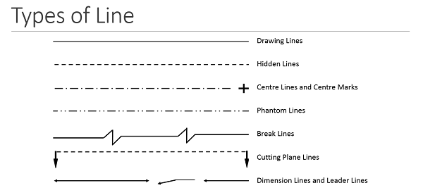
Following are the different types of lines used in engineering drawing. 4 When the observer looks at the object from above the view obtained is called top view TV or plan. Thin hidden lines are used as intermittent line types.
Learn more about the license 379. In general application thick lines are 06 mm 024. Through m draw a vertical projector to intersect the horizontal projector drawn through p at p.
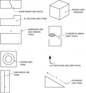
A type Continuos Thick B type Continuous THIN C type Continuous THIN Freehand D type Continuous THIN Zig-Zag E type Dashes THICK F type Dashes THIN G type Chain Thin H type Chain THIN and THICK J type Chain THICK K type Chain THIN Double Dash. Different line typesare used to depict the object. Table 1 shows the types and thickness of lines used for various purposes.
An extension line extends a line on the object to the dimension line. Used to indicate visible object of an object. Creative Commons Attribution-NonCommercial 40 International License.
The Bureau of Indian Standards has prescribed the types of lines in its code IS-10714-1983 to be used for making a general engineering drawing. A line such as a contour line drawn on a map and indicating a true constant value throughout its extent. Object lines solid depict features of the actual object.
Definition of isometric line. Working drawings are the set of technical drawings used during the manufacturing phase of a product. A scale is defined as the ratio of the linear dimensions of element of the object as represented in drawing to the actual dimensions of the same element of the object itself.
Some of the important Line types are elaborated below Line Types Object Line Solid thick line. These lines are used for the main lengths of the object view. Scales are used to make drawings of the objects to the proportionate size desired.
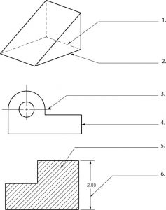
Object line Figure 3 Object lines Hidden lines. OBJECT OR VISIBLE LINES Thick dark line use to show outline of object visible edges and surfaces. An isometric view of a rectangular block is shown in Fig.
These thick solid lines show the visible edges corners and surfaces of a part. The corners of the block are used to position a line DF in space. Draw the projector line Draw the Front View p Y 1 Point in the First quadrant Procedure To project the right view on the left PP draw a horizontal projector through p to intersect the 45 degree line at m.
There are many other line types in common use. They contain all the information needed to. A common use is to specify the geometry necessary for the construction of a component and is called a detail drawingUsually a number of drawings are necessary to completely specify even a simple component.
A leader is a thin line used to connect a dimension with a particular area figure 24. Be used for most purposes on engineering drawings. Types of Lines The basis of any drawing is a line.
A variety of line styles graphically represent physical objects including visible hidden center cutting plane section and phantom. P is the right view of point P. The plan on which the projection of the object is taken is called the projection plan.
Sometimes they are used to make a drawing easier to understand. Each type of line has a very precise symbolic meaning. Three orthographic views in firstangle projection are given in Fig.
Object lines stand out on the drawing and clearly define the outline and features of the object. A quiz completes the activity. Often they are omitted in an isometric view.
A line representing changes of pressure or temperature under conditions of constant volume. The use of a right type of line results in a correct drawing. TV is seen on the HP.
Full Screen Basic Types of Lines Used in Engineering Drawings By Kelly Curran Glenn Sokolowski In this highly interactive object learners associate basic line types and terms with engineering drawing geometry. Usually terminates with arrowheads or tick markings. Hidden Line Dashed thin line.
One can not read a drawing by looking at one view. A single drawing is composed of many basic elements and different types of lines play distinct roles. In this case the relation between the dimension on the drawing and the actual dimension of the object is mentioned.
CONSTRUCTION LINE Very light and thin line use to construct layout work. 5 Side Views When the observer looks at the object from side ie from his left-hand side or right-hand side the view. Hidden lines dashed depict features that would otherwise not be visible in the view.
112 and it will be apparent that the projected length of the line DF in each of the views will be equal in length to the diagonals across each of the rectangular faces. An engineering or technical drawing is a graphical representation of a part assembly system or structure and it can be produced using freehand mechanical tools or computer methods. Thin lines are nearly 03 mm 012 in most technical drawings.
The actual type of material required is then noted in the title block or parts list or as a note on the drawing. The imaginary lines drawn from the object to the plane are called projectors or projection lines. The angle at which lines are drawn is usually 45 degrees to the horizontal but this can.
Some line types include. Used to extend the edge face or corner of a geometric feature. DIMENSION LINE Thin and dark lines use to show the size span of an object with a numeric value.
Lets see what types of lines used in engineering drawings.
The Language Of Lines Basic Blueprint Reading

Engineering Drawing Wikipedia
Quick Reference For Using Technical Drawings Scroll Saw Woodworking Crafts

Engineering Drawing Notes B Drawings Engineering Types Of Drawing

Engineering Drawing 8 Tips To Improve Engineering Drawing Skills
Line Conventions Manufacturinget Org
How To Read Engineering Drawings A Simple Guide Make Uk

Engineering Design And Cad A B Line Types Flashcards Practice Test Quizlet
0 comments
Post a Comment